Necessity
Though NVMe devices are now widely spread, SATA devices are majority. Most of the SSDs connected with PC using SATA interface, and definitely HDDs do. To get information about them, knowledge about their language, ACS(ATA Command Set) is mandatory.
Naraeon SSD Tools implemented based on SATA, and results from other devices converted to SATA form. When I refactor it I tried hard to delete characteristics of SATA, but I couldn’t get rid it at all.
In this article, I would only introduce issuing commands to SATA devices. Details would be written in next article.
In fact, ATA is not same as SATA, and SATA is different from ACS, but people commonly googles ‘SATA Command’ so I would use that wording.
ioctl code
As I said last time, to issue a command directly, driver should provide passthrough ioctl code. After XP SP2, OS provides these ioctl codes to do that.
Difference between two is the method. Former one is Buffered I/O, and latter one is Direct I/O. Buffered one reserves buffer with same size at system space, and process the I/O in that buffer. And direct one locks the pointed buffer and process I/O in there. I got in trouble using Buffered one with some of intel drivers. So I recommend direct one.
Input buffer
To place data buffer right after the passthrough struct, it is better to define a structure like this:
[snippet slug=ata_with_buffer lang=pascal]
Parameter includes paramters for ATA command, and Buffer is data buffer. Then just putting the pointer of the full struct into DeviceIoControl parameter would be okay. And it is also easy to calculate full buffer size.
Let’s see input structures on MSDN.
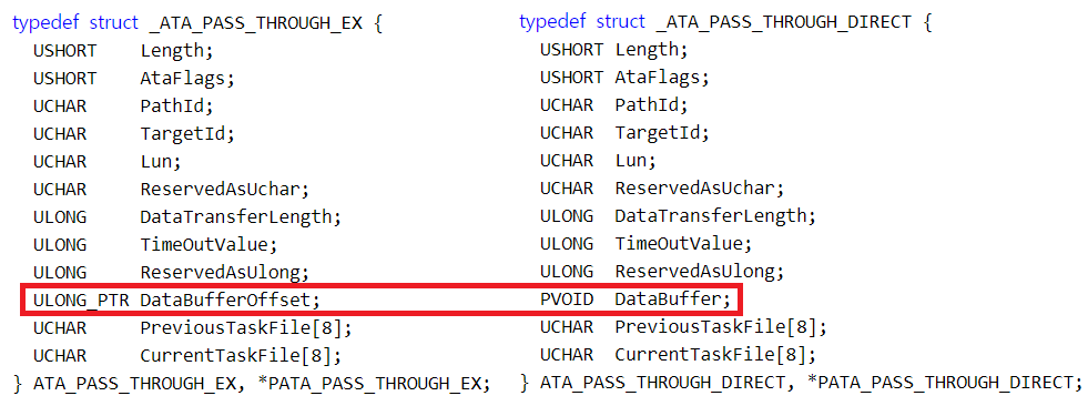
Input buffers of two ioctls (From: MSDN)
Two are very similar, but different in one item, buffer pointer. Buffered version requires DataBufferOffset, it means offset from the starting point of buffer to data buffer: sizeof(ATA_PASS_THROUGH_EX). And direct version requires exact pointer of data buffer.
Now we see details of PreviousTaskFile and CurrentTaskFile. Task File in the name means doesn’t mean file of file system, but means Task File of ATA Task File Register. ATAPI-7 V1 explains them in easy words. But commands we use don’t use them in their purpose. We need to fill them as the standard says in that command page. Next list shows the indexes of the registers(based on ACS-3).
- FEATURE: 0th
- COUNT: 1st
- LBA(low): 2nd
- LBA(mid): 3rd
- LBA(hi): 4th
- DEVICE: 5th
- COMMAND: 6th
- (Leave blank): 7th
Common commands only requires CurrentTaskFile to be filled. Just fill PreviousTaskFile array zeros. But if you use 48bit commands, you also need to fill PreviousTaskFile with Hi 24bit portion of LBAs. MSDN has so brief explanation of this, and you can think Previous means Lo portion, so be careful.
Other than that, you need to set these items.
- Length: Size of the parameter structure. By ioctl, it would be sizeof(ATA_PASS_THROUGH_EX) or sizeof(ATA_PASS_THROUGH_DIRECT).
- AtaFlags: Flag of the command. I would say about flags for each command in next article.
- PathId, TargetId, Lun: In ATA, normally leave blank.
- ReservedAsUchar, ReservedAsUlong: Leave blank.
- DataTransferLength: Sizeo of the data buffer.
- TimeOutValue: Set timeout in seconds. But in case of timeout, it would mean complete failure of the storage, and in that case timeout would not work. So I just put 30 in that.
After the buffer setting, use DeviceIoControl API and it would give us…
Output
Newbies would get an error. DeviceIoControl returns false. Then use GetLastError API to get the error code. And find the code in System Error Codes. Most of the error would be 1(ERROR_INVALID_FUNCTION) or 87(ERROR_INVALID_PARAMETER), those means you need to check all the parameters again. So don’t be frustrated if error gives you almost no information.
Then let’s think about output format. Overall, this standard uses little endian. In x86 case, there’s nothing to do with endianness. But problem is at string. Because that follows some weird byte order. It is saved in bytes, but each pair of bytes is swapped(Byte 1, Byte 0, Byte 3, Byte 2, …). See next picture to find the difference easier.

Left one shows the string after corrected. If not, you’ll get reversed string like right picture.
It’s caused by historical reason. Some of the 16bit integer embedded systems stores string in that order. And to make it easier to transfer them, ATA might chose that order. In fact, I wanted to know the reason for a long time. When I googled it, documents only says it is caused by some ‘historical reason’, and nothing explained about that. So I investigated deeper and got it.